by Allen Williams
This is somewhat of a departure from my typical product
evaluations because I did not buy the vendor system, I merely repaired
it. For those of you who are unfamiliar with Digital Command Control
products, it is a dedicated control system that breathes life into the
model railroad hobby.
Recently I was contacted by my adopted son who experienced an
operational loss of his model railroad command system. Because he had
bought a new house and had not been able to use it fairly regularly, as
with all electronic products, it simply died. When he turned the system
on there was no response. Checking the track power revealed less than a 1
volt output!
In his case, the system capacitors were suspect since that is usually
the first components that fail. I have had to fix many devices that I
purchased, including TV monitors and digital to analog converters so one
can view new digital programs on an analog TV, because the filter or other capacitors failed.
We live in a throw away society despite all the hoopla about 'green products' and re-cycling but the real problem is people don't fix things anymore, they just buy new. And manufacturers are quick to force this decision by making their products difficult or impossible to repair due to their choice and method of packing components.
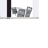
Model Rectifier Corporation has been an exception to the packed component
layout concept in
this market. Note the wide spacing and component oversize in their
arrangement. This not only makes replacement easier but dissipates heat
as well. The finned components left and right are transistor and SCR heat sinks.There is one switch (upper left) which turns on the power with the green diode, immediately right which indicates signal transfers and flashes to indicate shorts. The main chip (brains) of the system is just to the left of the two 500 Micro Farad (uf) capacitors.
Near the center of the board (bottom) is the green terminal for supplying power to the track.
Power capacitors seen from the bottom of the MRC board .
The capacitor to the left (off the board) is one that I replaced while I spot checked the fit (from the board bottom) of the largest 4700 uf capacitor.
The four largest capacitors are the ones I replaced. I also checked the
resistors and full wave rectifier bridge diodes for open or shorted
conditions.The photo shows the large 4700 Microfarad - uf filter capacitor (bottom of photo) as I checked the spacing in the printed circuit
underneath. Replacing this component raised the output to 1.6 VDC. It was not much of an improvement but it suggested the companion capacitor (1000 uf) maybe shorted. Actual testing revealed the second largest capacitor of 1000 uf was leaky so its installation brought the unit's voltage to around 22 volts!
The last picture is the small temporary layout consisting of some straight and curved track that I used to verify repair.The two 500 uf capacitors were also replaced (Lower left corner) which caused the unit to begin communicating with the MRC CAB controller. Once these signal capacitors began working the command unit began to develop the
correct 15 volt output.
Video of Test: https://www.sitejabber.com/reviews/modelrectifier.com#video_3599
Finally, I made a brief AVI film clip video on the repaired MRC system
to demonstrate how effective it was. I had talked to the MRC tech to get
specific responses regarding the system. I found them surprisingly
friendly and they gave me good information on how the various systems
interfaced. However, I was really surprised when the tech said the program
track section operated at 12 volts which could eliminate the need for a
program booster card. Sure enough, I was able to reset the decoder cab address on my North folk
and Western locomotive (but not with the Atlas Commander), used in my
short avi film to demonstrate the system repair. The locomotive had been
damaged some years ago during a short circuit derailment on my own
Atlas DCC system and my Commander failed to reset it. I had originally
thought that the brief short had damaged the locomotive.
The Atlas commander reduces the track voltage for its programming efforts to prevent chip damage if the locomotive decoder chips has not been installed.correctly.
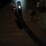
Physical Track Test Layout in Short Film Above
The last picture is the small temporary layout consisting of some straight and curved track that I used to verify repair. You can see the new 4700uf capacitor and its companion next to it in the lower right hand section of the board near the aluminum heat sink.
The locomotive is a Santa Fe FT- A diesel used to check the decoder registries. You can see the locomotive headlight is on correctly responding to the DCC command to turn the light on via the MRC controller. Once the unit began operating for about 30 minutes it started functioning like the original product.
Being able to affect a system repair so easily adds both life extension and value to the product and I would certainly recommend its purchase.
The MRC Prodigy Advance system is still available.
Tip for consumers
MRC stocks a number of NMRA DCC control systems, including the Prodigy Advance system I repaired, all economically priced.
Products used:
MRC Prodigy advance